Our trip for today was the Grimeton Radio Station:
Grimeton Radio Station is a UNESCO World Heritage site for being "an outstanding monument representing the process of development of
communication technology in the period following the First World War."
The Grimeton Station is a longwave radio transmitter that was built in 1922 to allow for Morse code communications over the Atlantic.
During the First World War, Sweden was limited in her ability to communicate internationally. The underwater communication cables were vulnerable to attack and, once cut, would render Sweden completely unable to communicate outside her borders. Realising the need to address this problem, the Swedish parliament made the decision to build the radio station in 1920.
The Alexanderson alternator was the chosen technology, invented by Ernst Alexanderson in 1906. This transmitted worked by means of a rotating electromechanical AC generator (the alternator) connected to an electric motor via a gearbox. The motor would turn the alternator at speeds sufficient to generate radio frequency alternating current which would then be send to an antenna.
The location of Grimeton was chosen for several reasons, the soil was good for building and radio wave conduction, it was far enough inland to prevent attack from sea, but most importantly it had a clear line to America over mostly sea, with no significant land masses to affect the signal.
 |
| (Picture from Swedish Wikipedia) |
The radio station allowed the Swedes to transfer Morse code messages across the Atlantic to the USA throughout the war years. It also allowed for telegrams from Swedes to family who emigrated to the USA (at the time there had been a large wave of immigration to the US from Sweden).
To send a telegram, the customer would leave the message with a local telegram office, who would telegraph or phone it through to the main office in Gothenburg. From there, the message would be transmitted to Grimeton. It would then be encoded into a punched ticker tape and fed into the Alexanderson transmitter. This process could occur in under 15minutes. The message would be received on Long Island, New York and could then be sent on to the destination in the USA. The reason for the use of tape was that the transmitter could send up to 400 words per minute, which was much faster than a person could input the code.
The radio operated at VLF (Very Low Frequency) of 17.2kHz with a wavelength of 17.4km. The callsign for the station was SAQ.
The technology for the radio was invented in 1906, and so was already dated and mostly obsolete by the time it was installed. The transmitter still works today, transmitting on World Peace Day (13th Feb), Alexanderson Day (late June/early July) and Christmas Eve (24th Dec), however there are concerns that many of the parts may no longer be able to be replaced if they fail.
In 1922, the Swedish government purchased the land from the local farmers, under the proviso that the farmers could continue to graze their cows around the antenna. The facility brought a large number of jobs to the area and despite initial concerns about the effects of the antenna, was generally well received. Construction finished in 1924, and two alternators were installed, to allow continual operation, even while one unit was undergoing maintenance. Each alternator is 200kW.
In order to transmit at a 17.2kHz frequency and with such a long wavelength, a large antenna was needed. This was achieved by means of six radio towers, each 127m tall, with the antenna running between them at a length of 1.9km.
Return signals were received at Kungsbacka in order to prevent interference between the transmission and receipt.
As time progressed, Grimeton acquired several shortwave transmitters also, allowing for additional communication to other countries.
The Radio Station was heritage listed as it is the only radio station still existing from the pre-vacuum tube era and it still functions.
 |
| One of the 6 Antenna towers, over the top of the visitor centre |
 |
| One of the 1960s shortwave antennas over the top of the main building |
 |
| Tom practicing Morse code |
 |
| The T-shaped towers are the main antenna. Other towers are for shortwave, radio and other signals |
Also in the auxiliary equipment, are two (now three as one is left over from the second transmitter) liquid resistors. These resistors were filled with a sodium carbonate solution and the fluid level could be raised or lowered to contact bars of various lengths inside the unit. This would change the resistance and this could be used to vary the speed of the alternator.
 |
| Liquid Resistor |
 |
| Cooling Pumps |
 |
| Morse ticker tape |
'
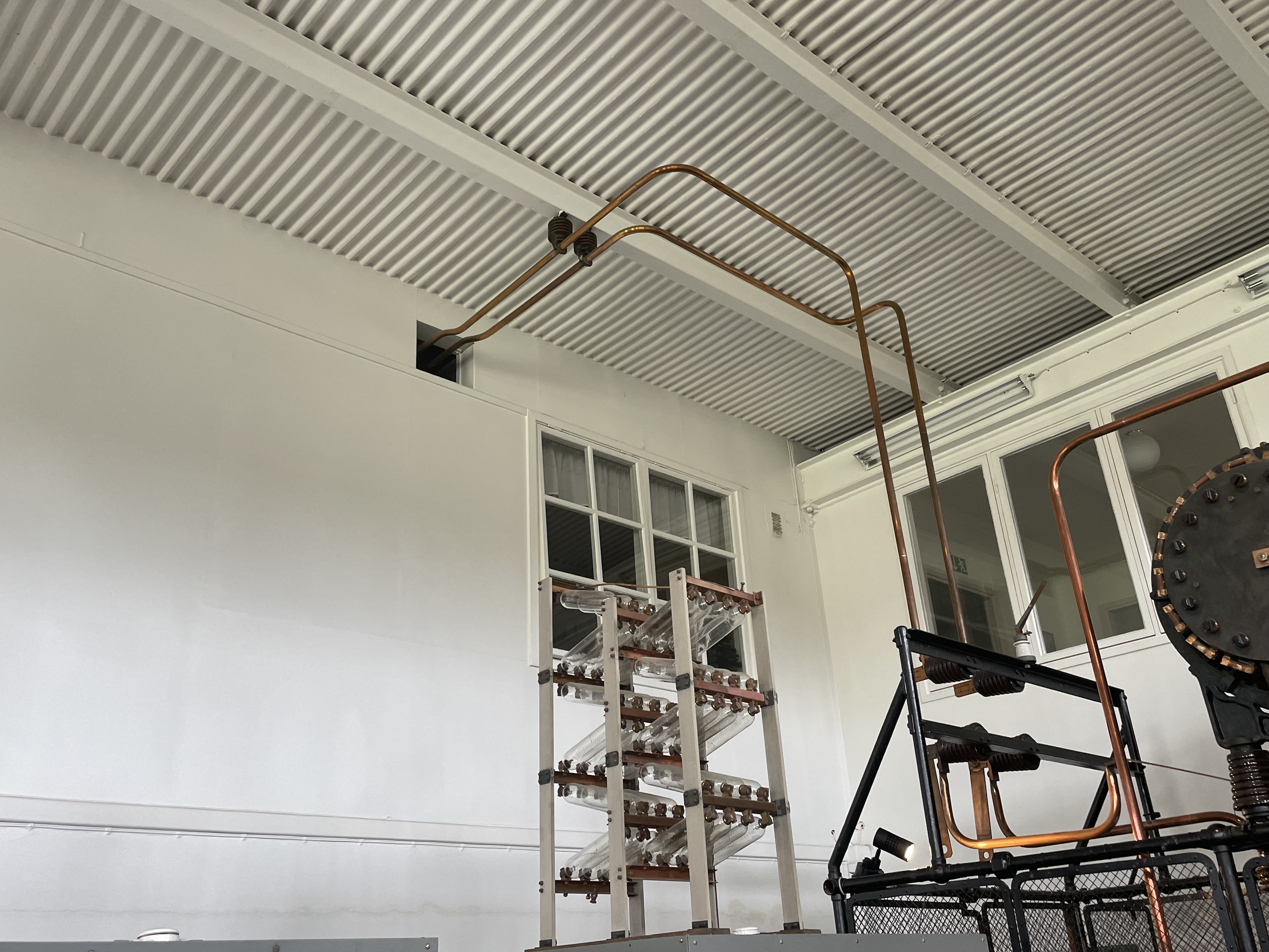
The signal from the transmitter passed through the magnetic amplifier before being fed through the copper pipes to the antenna outside.
 |
| Amplifier |
 |
| Copper transmission pipes |
The bunny ears on the top of the amplifier were used to bleed off any voltage spikes from a lightning strike or other surge:
 |
| Alexanderson Alternator |
The rightmost part of the transformer is the 500hp electric motor. This is connected to the central block - the gearbox which connects it through to the alternator (on the left). The alternator then rotates, generating the radio frequency signal that is passed through the amplifier and then onto the antenna.
 |
| Control Panel |
The control panel allows for control of the drive motor, DC generators, pumps and fans as well as displaying currents, voltages and speeds.
The leftmost section houses the main switches, the middle (from the two circle gauges to the ladder) is the switches, controls and indicators for the auxiliary equipment and the rightmost section is for speed control, antenna control and fine-tuning for the transmitter.
There was a small interactive game that allowed Tomas and I to run through some of the steps of starting the transmitter
Back outside the building, it was possible to see where the copper lines joined the antenna:
In winter, snow and ice on the antenna lines can affect the signal, so a de-icing system was built. This will run a high current through the lines to melt any snow or ice. It is housed in the small white shed below and connected to the main lines:
As well as the main Alexanderson transmitter, the main building also houses a series of shortwave radios, all labelled with a K number. These are used to contact other countries around the world
 |
| Callsigns for other countries - Paris, Rome, |
K5 - Is the Standard Radio ST-300-B with callsign SDK. It was in operation from 1942-63 with an output power 0.5kW and a frequency of 7-24MHz.
This transmitter was used to communication with the USA in the 1950s. Due to atmospheric interference between Sweden and the USA, signals passed through Tangier and were then forwarded to the USA.
 |
| K5 |
K6 - Is the Standard Radio CT-1500-A with callsign SDO. It was in operation from 1943-71 with an output power 1.6kW and a frequency of 3-9.5MHz.
K6 was the used to communicate with central European countries, such as Switzerland and Austria. This was the first transmitter to have externally supplied equipment allowing for free frequency selection. This frequency selection equipment needed more maintenance that then transmitter and was prone to failure. The other transmitters used technology developed by the station's staff.
 |
| K6 |
K3 - Is a Telefunken S 524 A with callsign SDA. It was in operation from 1939-65 with an output power 0.75kW and a frequency of 5.5-18.2MHz.
K3 was used to compliment the other transmitters. It was initially used to communicate with the Netherlands. After Norway and Denmark were attacked by the Germans, the transmitter was moved to Västergötland. It was returned in 1941 where it was used to communicate mostly with Italy. The frequency was often jammed and needed to be changed. The K3 unit contained three sets of coils that could be switched by key to quickly change frequency.
 |
| K3 |
K2 - Is a Svenska Radioaktiebolaget AK-142 F with callsign SDC. It was in operation from 1944-65 with an output power 0.8kW and a frequency of 3-12MHz.
K2 was mostly used to communicate with the Soviet Union and European countries behind the 'Iron Curtain', such as Czechoslovakia, Hungary and Poland.
 |
| K2 |
K4 - Is an AGA-Baltic 30838 with callsign SDQ. It was in operation from 1940-69 with an output power 40kW and a frequency of 7.5-18.7MHz.
K4 was mostly used to communicate with Asia: Japan, China and Thailand as well as Peru and to provide "press" transmissions to Swedish Merchant Ships.
The unit was modified in 1952 to also handle image and speech transmission in time for the Summer Olympics in Helsinki. In order to switch transmission modes, staff have to enter the unit. This made this the cause of most of the injuries in Grimeton.
 |
| K4 |
 |
| K4 |
K1 - Is a Collins Radio Company 202 A-1 with callsign SDE. It was in operation from 1938-65 with an output power 0.8kW and a frequency of 10-18.2MHz.
K1 and the original K2 (later replaced with the K2 above) were installed at Grimeton at the end of 1938 to allow for shortwave communication. These tube transmitters represented a new technology and soon took over a lot of the load from the Alexanderson transmitters. This change dramatically reduced the power consumption at the plant (approximately 20%). K1 was used to connected to the US and the original K2 was used to connect to the UK.
 |
| K1 |
K8 and and K9 are Marconi SWB 11/E transmitters, with callsign SDU and SDV respectively. They were in operation from 1946-71 with an output power 7kW and a frequency of 2-27MHz.
After the war, Sweden was able to purchase foreign radio equipment, and so four British Marconi transmitters were imported. While there were much more reliable, K8 was connected to a weather-sensitive antenna and hence was viewed as unpredictable. K8 was used to connect to Peru and Turkey.
The frequencies of the Marconi transmitters were adjusted daily in the morning and evening to account for atmospheric conditions. Messages about these adjustments were received from Radiocentralen in Stockholm via teleprinter.
 |
| K9 |
K10 and K11 is a Marconi SWB 11/X transmitters, with callsign SDN. It was in operation from 1948-74 with an output power 7kW and a frequency of 2-27MHz.
K11 was another Marconi transmitter, used mostly for countries to the South-East, such as Yugoslavia, Turkey and Lebanon.
K10 was fitted for telephony equipment, allowing international calls. In the morning K10 was used to call Japan and in the afternoon, calls to Argentina and Brazil.
 |
| K11 |
K12 is a Svenska Radioaktiebolaget AK-142 D transmitter, with callsign SDS. It was in operation from 1949-65 with an output power 0.8kW and a frequency of 3-12MHz.
K12 was originally the same model as K2, but it was upgraded to make modifications to reliability, capacity and service life. It was mostly used for telegrams to the Netherlands and Belgium.
 |
| K12 |
K7 is a Svenska Radioaktiebolaget AK-244 transmitter, with callsign SDR. It was in operation from 1944-70 with an output power 1.6kW and a frequency of 4-12MHz.
K7 was designed to be switched to different antennae to allow for communications around the world, such as Austria, Romania and Bulgaria. In 1965 it became the link to the Soviet Union.
 |
| K7 |


